
- About WIYN
- Observing at WIYN
Available Instruments
Optical Imaging
Infrared Imaging
Spectroscopy
Observing Tools
Observing Planning
At the Telescope
After Your Run
- Internal Use
WIYN Oversight
Calendars
ONE DEGREE IMAGER (ODI)
Tools For Proposing to use ODI and Planning Your Observing Run
Layout - The layout of detectors is shown in the following diagram. Each shaded square is an active detector (blue: Lot 7, green: Lot 6, grey: Lot 3). The other 34 locations in the focal plane have been covered with black plates. This can be seen in the photo of the focal plane (image credit: University of Arizona Imaging Technology Laboratory David Ouellette, Yvonne Holguin, and Michael Lesser) below the diagram.
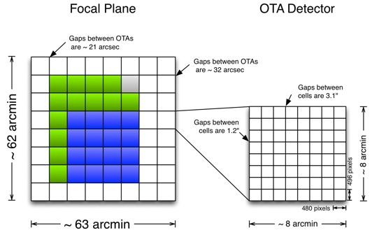
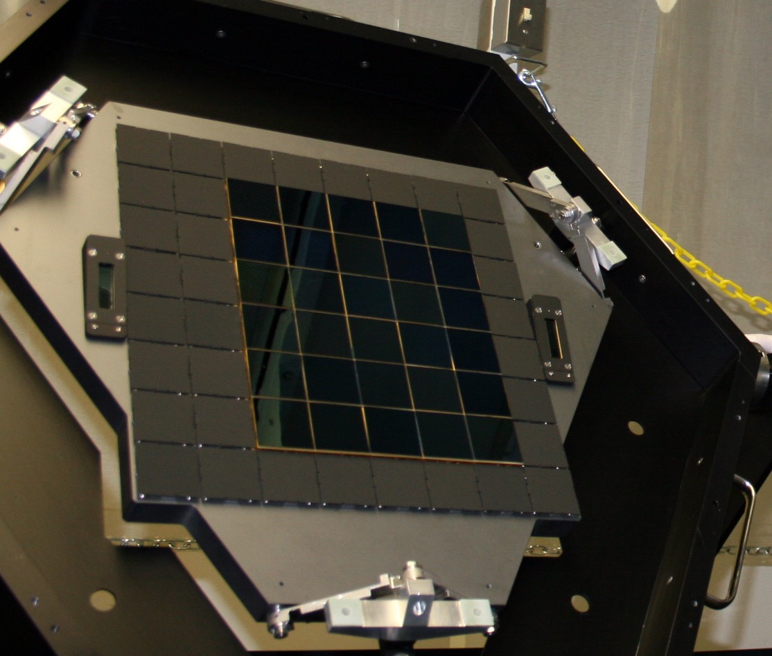
The total imaging area is about 40 x 48 armin square, however, at least one detector must be dedicated to acquire a guide star. Please refer to the ODI User Manual for the performance of individual detectors and the location of bad cells / columns.
Gaps - Because of the gaps between cells and between OTAs, it is necessary to take multiple offset exposures (a dither sequence) in order to produce, in the end, an image with the gaps filled in. A minimum of 9 exposures with different pointings are needed to do a reasonable job of filling in the gaps.
Distortion - The distortion is significant, though not as bad as the 4m CCD Mosaic Imagers. Like the 4m corrector, the magnification increases with distance from the optical axis, though it is only about a 4% effect between the center of the field and the extreme corners. The central pixel scale is 0.113 arcseconds/pixel.
Noise/full well - Each cell has its own amplifier, and so the gain and noise varies a bit from cell to cell. We measure 7-11 electrons noise and about 70,000 electrons full well for all the cells. The gain is in the range 1.2-1.6 electrons per ADU.
Filters - We have 9 full-size filters, SDSS u', g', r', i', and z', NB695, NB422, NB746 and H-alpha. These large filters cover all OTAs.
Photometric Zero Points - We have measured preliminary photometric zero points. This is the magnitude in a given band that will produce 1 detected electron per second when observed at an airmass of 1.0. Equivalently, it is the constant to be added to -2.5 log count/sec (corrected to airmass=1.0) to get the apparent magnitude of the object measured. These preliminary numbers are:
- g' 26.7
- r' 26.6
- i' 26.1
- z' 25.1
Note that these magnitudes are in the SDSS system, close to AB magnitudes.
Exposure Time Calculator - Daniel Harbeck has produced an exposure time calculator (https://www.wiyn.org/ODI/wiynODIetc.html) in which we have inserted our measured zero points.
Vignetting - Although there is no vignetting within a one degree diameter circle, the outer OTAs are further from the center than that. We have only seen evidence of vignetting (~50%) in the one OTA that is in the true corner - the bottom right in the diagram illustrating the layout above.
Crosstalk - With multiple detectors and controllers, there is the possibility that a strong signal from a bright object in one device will contaminate another image. We have measured this crosstalk, and we find that it is (a) confined to the seven other cells in the same row as the cell with the bright object, and (b) even in those cells, it is at a level of about 1/10,000. That is, a saturated pixel produces a crosstalk "ghost" of six ADU in the other cells in its row. This is less than the read noise, and it can only be seen visually when there is an extended saturated region. The reduction pipeline removes this effect.
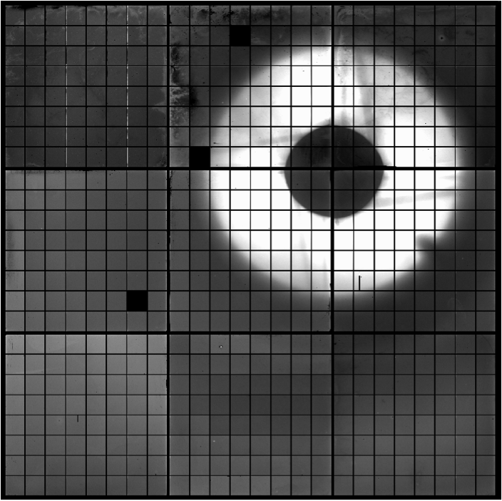
Pupil Ghost - Reflections between the filters and the Dewar window result in pupil ghosts in some images. These ghosts are different depending on which level (1, 2, or 3) a given filter is in. Generally, the ghost is only significant for filters in layer 2 (see image of science field). In layers 1 and 3 it is much more diffuse and out of focus. It also depends on the filter. The layer 2 pupil ghost has an intensity of about 10% in g, 4.5% in r and z, and 0.5% in i. The ghost is removed by dividing the flat field by a template of the pupil ghost illumination pattern, and by subtracting a scaled template from the science observations.
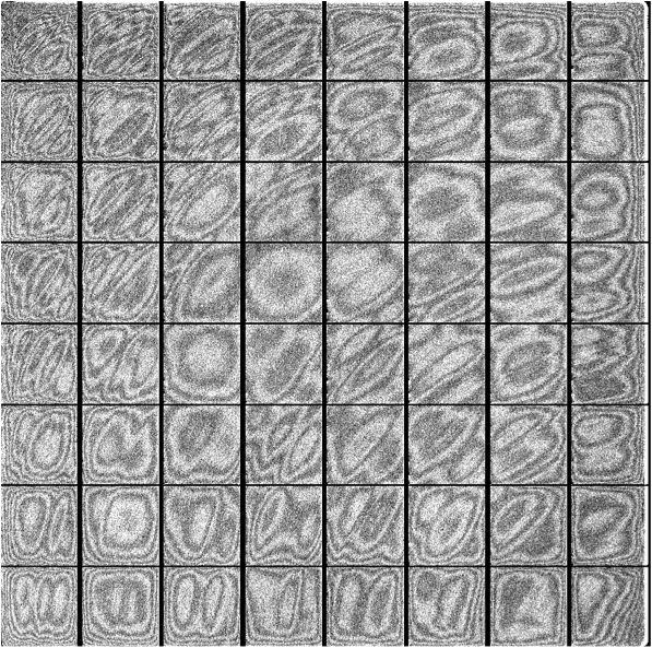
Fringing - Fringing is seen in the z band (P-V ~ 5%) and in the i band (~0.5%). It can be removed with images generated from dark sky exposures from which sources have been removed.
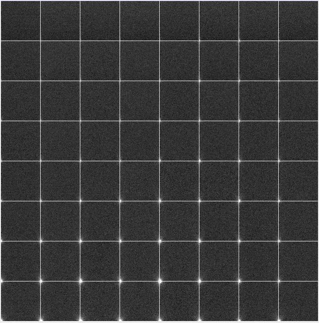
Glows/biases & darks - One of the deficiencies of the detectors in ODI is that some of the non-imaging circuitry glows. The brightest of these is the amplifiers, one per cell. This glow can be reduced during a static guiding exposure by turning the amplifiers off. However, the amplifier has to be turned on again to read out the cells at the end of the exposure. This glow is quite well removed by subtracting a bias frame from the science image. Shown below is a typical bias frame (only one of the 30 OTAs shown). It can be seen that the glow is brighter at the bottom of the detector because these are the cells that are read out last. A typical cell from the center of this OTA has about 100,000 electrons from each amplifier. However, that signal is spread over a large region. Only about 60 pixels have 100 electrons or more, which is probably the minimum sky level in a short exposure. Sixty pixels correspond to about 0.02% of the area of the cell.
In addition to the amplifiers, there are two transistors associated with each cell that glow. The image below is a 1200 second dark, showing a number of cosmic rays in addition to the glowing transistors. Although these glows look bright, they are swamped by the sky in a broad band exposure. They are quite effectively removed by subtracting a dark frame.
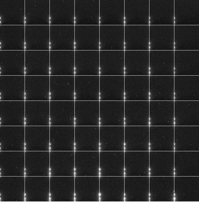
Image Quality - Image quality is primarily limited by the seeing. The best images we have seen have FWHM of around 0.4 arcseconds in the i' band. The FWHM measurements are quite uniform over the entire focal plane. An ADC can be used to improve the image quality at high airmass.
Guide Stars - There is a very effective interface for autoatically or manually selecting suitable guide stars. Guide stars will have to be about mag=14 or brighter, and it may be advantageous to use several distributed around the outside of the field, in which case the guide signals are averaged. OTAs from which guide star video is read out must have their amplifiers turned on, and so they will glow much more. However, their data may still be usable, though the cell with the guide star will be missing. Currently, there is about a one minute overhead on each exposure to set up the guiding in manual moded, and a few seconds for the (still experimental) automatic mode.
CTE - The detectors up to Lot 6 have a minor shortcoming in that their vertical CTE is poor when the background is very low. This means that below that background level, images will be smeared vertically, with trails of charge "above" them. The threshold at which this effect vanishes is about 100 electrons per pixel, which is reached in less than one minute in a broad band exposure. This issue has been repaired for Lot 7 detectors, and observers expecting a low background signal (narrow band filters, short exposures) should place their target of interest on the Lot 7 detectors in the focal plane.
Readout Time - The entire ODI focal plane is read out in about 30 seconds. It is possible to queue multiple exposures to minimize the overhead.
Calibration plan - Data from ODI will be automatically transported to the ODI-PPA archive in Indiana. There it will be pipeline processed to remove the instrumental effects described above, and it will be made available through the ODI-PPA portal. Access will be granted immediately to the PI and Co-Is, and will be granted after a proprietary period (normally 18 months) to other researchers. In order to support long term scientific use of ODI data, observers are required to obtain a set of calibration data according to a standard calibration plan. For the most part, these are the calibration exposures that one would take anyway - biases, darks, and dome flats (in the afternoon) and a minimum set of photometric standards (about 20 minutes at the beginning of the night).
Contact for questions - questions about ODI should be addressed to the ODI Instrument Scientist.


Last modified: 11-Mar-2021 12:41:07 MST
- Observing at WIYN